What we will do:
This post discusses how to set up the LCD4 Cape with the Circuitco ADC cape for the Beaglebone Black. It is currently not straightforward and requires recompiling the Beaglebone Kernel. Adding ADC is important if the LCD4 touchscreen is being used, which ties up all onboard ADC. The Circuitco ADC cape communicates through the Serial Peripheral Interface (SPI) and adds 8 ADC ports.
Know your kernel:
As of the writing of this post, the Beaglebone Black (BBB) kernel is under continuous development and is constantly changing. Many writeup tend to be accurate for only a short period of time, so to be clear:
NOTE: This process was successful using the following:
- BBB Rev. C
- Linux beaglebone 3.8.13-bone67 (Debian)
- 4d Systems 4DCAPE-43 (should work on any cape using the
The source of the problem:
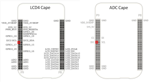
One would expect that the capes would just stack on top of each other an work out-of-the-box; however, there is an issue in the BB-BONE-LCD4-01-00A1 (and BB-BONE-LCD7-01-00A1 for that matter) that ties up P9_21 which is required to read the SPI. First, it is clear from the documentation that this pin is not required to use this model of LCD screen. The pin layouts can be found:
- ADC Cape pin layout
- 4d Systems 4DCAPE-43 pin layout on page 3
So the hardware doesn’t conflict; however if we look at the device tree BB-BONE-LCD4-01-00A1.dts we will find three lines:
- “P9.21”, /* keys: gpio0_3 */ at line 47
- “gpio0_3”, at line 54
- 0x154 0x2f /* P9_21 spi0_d0.gpio0_3 INPUT | PULLDIS | MODE7 */ at line 105
These lines are setting up the device tree to have exclusive use of p9_21 and setting the pin to MODE7 which is the pin muxing implemented on the beaglebone. This can be seen in the reference manual for rev. C in table 13:
For the SPI0 (and for the UART2 for that matter) we need Mode 0 (or Mode 1) but the LCD4 device tree is taking exclusive use of the pin and setting it to Mode 7 for the gpio[3], which is then does not use.
So the LCD4 dts file needs to be edited, and we used to have access to the file with the rest of the device trees in:
debian@beaglebone:/lib/firmware$
However, it turns out that that access didn’t matter anyway because the BBB has a precompiled version of the LCD4 device tree that it uses and is inaccessible.
The solution:
To get the SPI working on the BBB we need to recompile the whole kernel. Thankfully, Robert Nelson has made this so easy that even I could do it. The directions are here.
When I followed these direction I did not build the SD card structure from scratch. I, instead, installed a precompiled image onto the SD card using these instructions here. I used the Image from 2014-10-22. The key here is to choose the kernel that matches the one you are editing. This is probably a discouraged practice but it saved me a lot of time.
If you have a 3.8.13-bone67 image already installed on the SD card (and your tool chain is already set up; DO NOT SKIP the 32 bit gcc library step like I did), then you can start at Linux Kernel. There are directions for 2 versions here:
- am33x-v3.8
- am33x3.17
as of the writing of this post there wasn’t a campmgr or a reasonable substitute for it on the am33x3.17 (I think) so use the use the am33x-v3.8. The dts you want to edit is in:
debian@beaglebone:/bb-kernel/KERNEL/firmware/capes
so:
nano BB-BONE-LCD4-01-00A1.dts
and remove:
- “P9.21”, /* keys: gpio0_3 */ at line 47
- “gpio0_3”, at line 54
- 0x154 0x2f /* P9_21 spi0_d0.gpio0_3 INPUT | PULLDIS | MODE7 */ at line 105
save the file and close it. Robert has provided one more useful shell script that he talks about in his README.txt to rebuild the kernel without resetting the changes to the dts, which is located in the tools folder. So:
- ./build_kernel.sh
- edit .dts file as stated above
- ./tools/rebuild.sh
now the freshly compiled kernel should be in:
/bb-kernel/KERNEL/arch/arm/boot
and the instruction under section Copy Kernel Files can be used to replace the correct files from the original image with the new kernel.
sudo cp -v ./bb-kernel/deploy/${kernel_version}.zImage /media/rootfs/boot/vmlinuz-${kernel_version}
sudo tar xfv ./bb-kernel/deploy/${kernel_version}-dtbs.tar.gz -C /media/rootfs/boot/dtbs/${kernel_version}
This should boot up the new kernel with the replace device tree and now the pin is free.
Do not forget the SPI device tree:
There is one last thing that has to be done, which is to activate the SPI device tree. You can do it directly with the capemgr.9 with instructions here.
root@beaglebone:/# cat /sys/devices/bone_capemgr.9/slots
This will show you what is attached. The LCD4 Cape should now be listed here. To add the SPI device tree:
cd /lib/firmware
echo ADAFRUIT-SPI0 > /sys/devices/bone_capemgr.9/slots
You can also have it load automatically by following the instructions under Loading custom capes by opening:
nano /etc/default/capemgr
and adding the line:
CAPE=ADAFRUIT-SPI0


Thank you very much!
Just yesterday, found that SPI0 is not working after connecting 4DCAPE-43. Your post helped me to deal with this problem.
LikeLike
AWESOME! I’m glad :-). If anything could be made more clear please let me know.
LikeLike
For more clarity, write this post on Russian 🙂
Unfortunately, I can not work with the BBB During the next week. After returning, I repeat your experiments and write here about the results.
Thanks again.
LikeLike